1. The accompanying figure shows some electrical appliances connected in a circuit in a house. Answer the following questions.
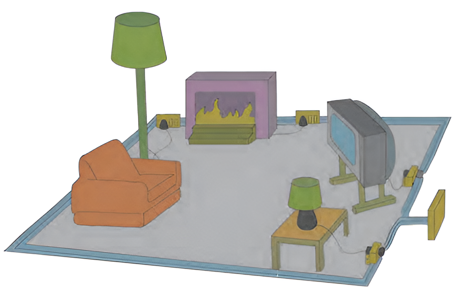
A. By which method are the appliances connected?
Answer. Parallel connections
B. What must be the potential difference across individual appliances?
Answer. The same as the supply voltage.
C. Will the current passing through each appliance be the same? Justify your answer.
Answer. Different in general. We have I = V/R. Even if the voltage (V) is the same, the resistance (R) can be different. Hence, the current (I) through each appliance may not be the same.
D. Why are the domestic appliances connected in this way ?
Answer. Even if one of the appliances is out of order, other appliances can be used.
E. If the T.V. stops working, will the other appliances also stop working? Explain your answer.
Answer. Even if the TV stops working, other appliance will not stop working as they are connected in parallel across the supply.

2. The following figure shows the symbols for components used in the accompanying electrical circuit. Place them at proper places and complete the circuit.
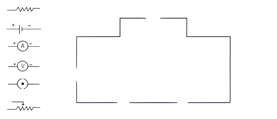
Which law can you prove with the help of the above circuit?
Answer.
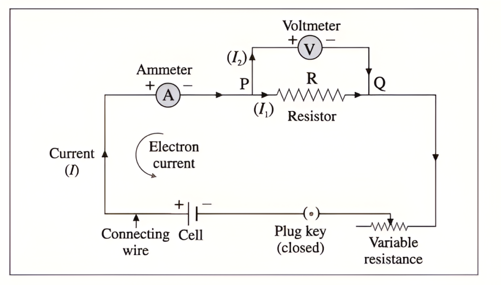
Ohm’s law can be verified with the help of the above circuit.
3. Umesh has two bulbs having resistances of 15 W and 30 W. He wants to connect them in a circuit, but if he connects them one at a time the filament gets burnt. Answer the following.
A. Which method should he use to connect the bulbs?
Answer. Parallel combination.
B. What are the characteristics of this way of connecting the bulbs depending on the answer of question A above?
Answer.
Characteristics of a parallel combination of resistors :
(1) The voltage (potential difference) across each of the resistors is the same.
(2) The total current is equal to the sum of the currents through the individual resistors.
(3) The reciprocal of the effective resistance of the combination is equal to the sum of the reciprocals of the individual resistances.
(4) The effective resistance of the combination is less than any of the individual resistances.
(5) The current through each resistor is inversely proportional to the resistance of the resistor.
(6) This combination can be used to decrease the resistance in a circuit.
C. What will be the effective resistance in the above circuit?
Answer.
4. The following table shows current in Amperes and potential difference in Volts.
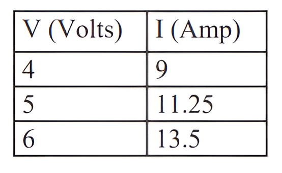
a. Find the average resistance.
Answer.
b. What will be the nature of the graph between the current and potential difference? (Do not draw a graph.)
Answer. A straight line passing through the origin (0, 0).
c. Which law will the graph prove? Explain the law.
Answer. Ohm’s law. I ∞ V.
5. Match the pairs
‘A’ Group ‘B’ Group
- Free electrons a. V/ R
- Current b. Increases the resistance in the circuit
- Resistivity c. Weakly attached
- Resistances in series d. VA/LI
Answer.
(1) Free electrons – Weakly attached
(2) Current – V/R
(3) Resistivity – VA/LI
(4) Resistances in series – Increases the resistance in the circuit
6.The resistance of a conductor of length x is r. If its area of crosssection is a, what is its resistivity? What is its unit?
Answer.
7. Resistances R1, R2, R3and R4 are connected as shown in the figure. S1 and S2 are two keys. Discuss the current flowing in the circuit in the following cases.
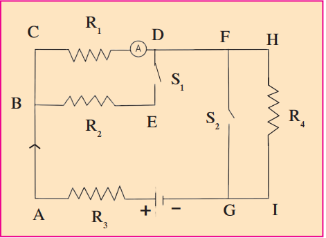
a. Both S1 and S2 are closed.
Answer.
(a) When both S1 and S2 are closed, the effective resistance of the circuit decreases and hence, current will increase.
(b) When both S1 and S2 are open, the effective resistance of the circuit increases and hence, current will decrease.
(c) When S2 is closed and S2 is open, the effective resistance of the circuit decreases and hence current will increase. [Current will be more than case (b) but less than in case (a)]
8. Three resistances x1 , x2 and x3 are connected in a circuit in different ways. x is the effective resistance. The properties observed for these
different ways of connecting x1 , x2 and x3 are given below. Write the way in which they are connected in each case. (I-current, V-potential difference, x-effective resistance)
a. Current I flows through x1 , x2 and x3
b. x is larger than x1 , x2 and x3
c. x is smaller than x1 , x2 and x3
d. The potential difference across x1, x2 and x3 is the same
e. x = x1 + x2 + x3
f. x = 1 / (1/x1 + 1/x2 + 1/x3)
Answer.
(1) Series combination.
(2) Series combination.
(3) Parallel combination.
(4) Parallel combination.
(5) Series combination.
(6) Parallel combination.
9. Solve the following problems.
A. The resistance of a 1m long nichrome wire is 6 W. If we reduce the length of the wire to 70 cm. what will its resistance be? (Answer : 4.2 W)
Answer.
R = ρ L / A
Since the material and area remain the same:
R1 = ρ L1 / A
R2 = ρ L2 / A
Therefore:
R2 / R1 = L2 / L1
R2 / R1 = 0.7 / 1 = 0.7
R2 = 0.7 × R1
R2 = 0.7 × 6 Ω
R2 = 4.2 Ω
B. When two resistors are connected in series, their effective resistance is 80 W. When they are connected in parallel, their effective resistance is 20 W. What are the values of the two resistances? (Answer : 40 W , 40 W) ( in answer ^ this means square)
Answer.
R1 + R2 = 80
(R1 × R2) / (R1 + R2) = 20
(R1 × R2) / 80 = 20 R1 × R2 = 1600
R1(80 – R1) = 1600
80R1 – R1^2 = 1600
R1^2 – 80R1 + 1600 = 0
(R1 – 40)^2 = 0 R1 = 40 Ω
R2 = 80 – 40 = 40 Ω
C. If a charge of 420 C flows through a conducting wire in 5 minutes what is the value of the current? (Answer : 1.4 A)
Answer.
Q = 420 C
t = 5 minutes = 5 × 60 = 300 s
I = Q / t
I = 420 / 300
I = 1.4 A